
(中文翻译附后)
A Combined Retaining Structure and Its Application
in Deep Excavation
Yuwen Yang
Senior Geotechnical Engineer, Wuhan Geotechnical Engineering and Surveying Institute, Wan Song Yuan Road 209#, Hankou, Wuhan, 430022, China; wayneywyang@hotmail.com
ABSTRACT: In a combined structure, soil-nailing wall retains the upper and shallow soil while propped piles at the toe of the wall augments the overall stability of ground in deep excavation. Although such a structure developed from soil nailing wall plus internally-braced pile has widely been employed, it is regarded as not an integral structure, but a separate one to analyze and calculate. This treatment is unreasonable. By the numerical experiments, the combined structure is explored about its space earth-retaining mechanism as the integrated system. Analytical results indicate that the actual earth pressure exerted to the structure is different with that determined by Rankine’s theory. The distribution of Rankine’s pressure is adjusted to accommodate the calculation results. A case study proves the validity of the adjustment.
INTRODUCTION
The combined structure in this paper refers to the earth-retaining wall developed from soil nailing wall plus internally-strutted piles, where soil nailing wall is used to retain the upper soils while the internally propped piles provide overall stability to ground in deep excavation. Such a structure is usually applied to the geological conditions: (1) top soil is the high strength fill, underlying which, there is soft soil and (2) underground facilities or nearby buildings are in close to the excavation and necessary to protect.
For stability and deformation analysis of soil nailing wall, many scholars have developed a variety of methods (Bridle, 1989; Yang et al, 1998; Yuan et al 2003 ), among which, the limit equilibrium method is popular. Pile wall is a traditional earth-retaining type, and the elastic spring resistant approach is widely used to predict pile deformation and earth pressure. However, to the combined structure which will be discussed, its retaining mechanism is different with either pile wall or soil nailing wall. Due to the upper soil restrained by soil nailing wall, the pile can be designed to be shorter. Correspondingly, pile wall adjacent to the toe of soil nailing wall improves the overall stability of ground. It is difficult to consider the influence of stability of soil nailing wall on the lower pile wall or effect of pile resistance at the wall toe to soil nailing wall above. So the mechanism of the combined structure has still remained unknown. In this paper, use FLAC for numerical simulation to explore its features such as deformation, soil stress, and pressure during excavation.
NUMERICAL SIMULATION
Assumptions
In the combined structure, soil nails, facing, pile, binding beam, internal props constitute a spatial structure as a whole to bear earth pressure and restrain excessive deformation. In order to reduce the volume of calculations and highlight main factors, the reasonable simplification for the issue is necessary. The assumptions are made in the following. (1) it is plane strain problem in homogeneous soil; (2) pile top is directly connected with prop neglecting existence of binding beam; (3)except soil, all the structural elements are assumed to be elastic. Soil adheres to Mohr - Coulomb yield criterion; (4) neglect overload on the ground, and (5) neglect groundwater.
The binding beam directly linked with the tops of the adjacent piles transmits axial force of prop to pile tops and almost does not play a role in retaining. In addition, in the following numerical simulation, there is only one pile to involve. The effect of neglecting the binding beam on the calculation is limited.
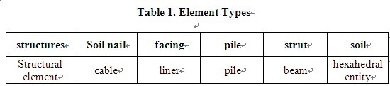
Element types
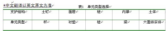
Table 1 illustrates the types of structural elements to represent the combined structure. Soil nails are slender, flexible, and can be simulated by cable. The 100mm-thick facing may be separate with soil in active zone if large displacement occurs in soil nailing wall. There is the coupling effect, and so liner structural element is applied to represents the facing layer. Pile wall is directly in use of pile element. Pile and the surround soil can be separate or close and there is also the coupling effect. Use beam element to represent the prop. Soil body is discretized into a series of cubes of hexahedral elements to improve the calculation accuracy. These structural elements are of basic features: beam element, the two-node straight-line element, can withstand axial force, shear, bending moment; cable element, the two-node straight-line unit, only to bear axial force, is mobilized with the surrounding soil through the interaction of frictional resistance; pile element, the two-node straight-line unit, similar to beam element, can also interact with the surrounding soil in separation or closure; liner element, three-node plane element, interacts with the surrounding soil in normal and tangent directions to separate or slide according to Mohr-Coulomb yield criterion. The combined structure consists of soil, a pile, 4 rows of soil nails, facing and one prop.
In numerical simulation, construction steps can be taken account. For soil nailing wall, while excavating, soil nails are installed one row by one row simultaneously forming the shotcrete facing. When excavation proceeds to a given depth, install a pile at the toe of the wall and then set a prop to link the top of the pile. At the sixth step of excavation, install the pile; at the seventh step, set up the internal prop.
Simulation extent
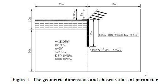
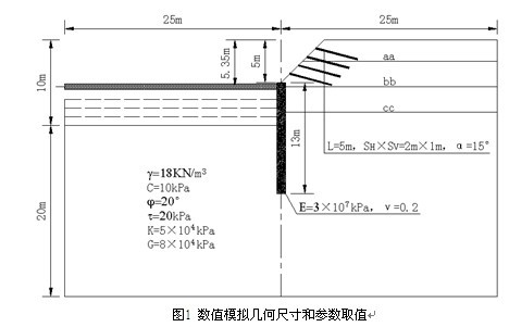
As shown in Figure 1, the combined structure of the soil nailing wall plus pile wall is employed in a 50m-wide rectangular excavation in homogeneous soil with the final excavation depth of 10m. There are total steps of 10 to excavate, 1m deep each step. The structure is assumed to be thickness of 2.0m as a plane strain problem. The area of simulation is 50m × 30m. The simulation boundary is extended to 20.0m under the base of pit at last step (see Figure 1).
The values of parameters
Figure 1 shows the geometry of the structure and some of parameters used in simulation. The values of the parameters are in line with the actual conditions. The remaining parameters are given as below.
(1) Soil nailing wall. In the extent of simulation, there are four 5m-long soil nails in spatial arrangement SV × SH = 2.0 × 1.5m2, made from Φ22 steel bars with elastic modulus E = 2 × 10⁸kPa and yield strength fy = 1.86 × 10⁷kPa. Soil nails are installed in inclination of 15 ° to the horizontal. Pre-drilled holes with diameter D = 0.12m to insert soil nails are filled with cement mortar in C20. Soil nails are mobilized with surrounding soil up to the ulltimate frictional force = 15kPa. 100mm-thick facing layer makes up of reinforced concrete in C20 with elastic modulus E = 2.55 × 10⁷kPa and Poisson's ratio = 0.25. The normal and tangential stiffness between facing and the surrounding soil are assumed to be 100kPa / m , respectively, and their cohesive strength 2kPa. (2) Pile. There exists a single pile with diameter of 1000mm and the central spacing of 2.0m, made from reinforced concrete in C30. Pile interacts with surrounding soil in the tangential and normal stiffness of 100kPa / m, 10000kPa / m, cohesive strength 10kPa, friction angle 20 °, respectively. (3) Prop. only one prop is assumed to support the extent of 20 piles. The prop is rectangular in cross-section of 500 × 700mm2, made from reinforced concrete in elastic modulus of 2.55 × 10⁷kPa and Poisson's ratio of 0.25.
Computational results
Figure 2 illustrates settlement δV and horizontal displacement δH at depth H = 5m, 10m, respectively. At H = 5m, the maximum horizontal displacement is below the base of pit, δHmax = 25mm, and the largest settlement is at the boundary, δvmax = 15mm. At H = 10m, δHmax is near the bottom (δHmax = 70mm), and the largest settlement δvmax = 35mm also locates in the boundary. With increase in the excavation depth, deformation of soil nailing wall increases, but the distribution shape is kept to be similar. Location in maximum horizontal displacement is not near ground surface, but close to the base of pit. This is due to soft soil to cause bottom uplift. At the different depths of excavation, if deformation in pile wall increases, displacement for soil nailing wall also increases.
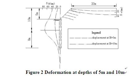
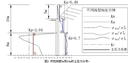
Figure 3 illustrates coefficient distribution of the earth-pressure at depth H = 5m, 10m, respectively, where K0 is coefficient of earth pressure at-rest, K0 = 0.7; Ka indicates coefficient of active earth pressure , Ka = 0.49; Kp is coefficient of passive earth pressure, KP = 2.04; σH5 and σH10 represent horizontal stresses exerted to the retaining structure at depths of H = 5m, 10m, respectively. and represent the self-weight stresses back and in front of the combined structure. is calculated from ground surface and from the base of pit.
Figure 3 shows that at depth of H = 5m, the earth pressure exerted to the facing of soil nailing wall is far less than the values of Rankine’s active earth pressure. At H = 10m, the distribution of σH10 is complicated and there are two turning points, locating around the prop and near the middle of passive zone, respectively. Under the base of pit, the value of earth pressure from simulation is greater than that from the Rankine’s theory and close to the earth pressure at-rest. Close to pile base, σH10 does not increase and essentially remains unchanged. Accordingly, within the extent of 3m in the passive zone, σH10 is larger than that from Rankine’s theory. Comparing to the passive earth pressure in pile wall (Hashash et al, 2002 ), the value of passive earth pressure in pile wall in the combined structure increases by about 20%. This is due to the existence of soil nailing wall above the pile. The curves in Figure 3 also illustrate that the values of earth pressure applied to the facing of soil nailing wall decreases with increase in excavation depth, but the maximum value decreases by almost 50%, compared with that from Rankine’s theory. This proves that the pile and the soil nailing wall interact to keep stability of ground during excavating.
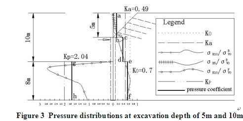
To braced excavation, Terzaghi and Peck proposed a semi-empirical formula to predict the load on retaining structures (Craig, 2002). This paper involves the combined structures, whose characters are more complicated than only pile in braced excavation. Due to the prop to restrain deformation of ground, the soil in the vicinity of the prop may not have entered the plastic state and so Rankine’s theory is not applicable to predict the earth pressure. Soil body near the base of pit is affected less by the prop and likely to enter the plastic state and the Rankine’s theory is appropriate. Near the pile base, because of the embedding effect of soil in active zone, soil body is inadequate to move and it seems to not apply Rankine’s theory. Numerical simulation results show that (see Figure 3), at H = 5m, the facing in soil nailing wall is subjected to the earth pressure less than that determined by Rankine’s theory. With increase in excavation depth, due to the pile near its toe to limit displacement of soil around, the pressure acting on the facing decreases, as shown in Figure 3. at H = 10m, around the base of pit, the earth pressure is close to that conducted by the Rankine earth pressure theory, while near the prop and pile base, the earth pressure is larger. Therefore, as shown in Figure 3, the pile along its depth in the active zone can be divided into three sections: ab, cd, ef, and in passive zone gh to amend coefficients of the earth pressure determined by Rankine theory as follows:
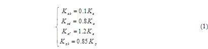
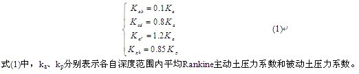
In equation (1), the signs ka, kp represent the average coefficient of active earth pressure and passive earth pressure coefficient from Rankine’s theory along excavation depth, respectively.
CASE STUDY
Overview
The Jianghua residential complex building was surrounded by Sanyang Road to the north, Zhongshan Road to the east, a tall building near Jinghan Road to the west. The project consisted of one 13-storey, one 15-storey, one 2-storey office buildings, as well as three 18-storey residential buildings, with two-storey basements to extend the total area. Layout of these six buildings was similar to the "courtyard", China’s traditional house type. The basement in perimeter of 516m is rectangular in shape occupying an area of about 14400m2 with depth of 9.4 m to10.6m. To the north and to the east, there existed underground pipes or cables very close to excavation boundaries. These nearby underground facilities are necessarily protected to avoid damage during excavation.
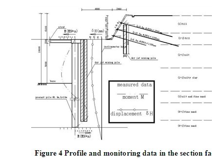
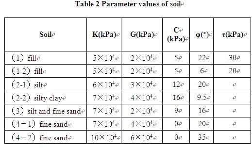
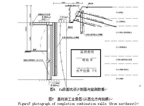
Take the section fa, close to Sanyang Road, as an example to illustrate the geology on site. Strata related to excavation from ground surface included (1) fill; (1-2) fill; (2-1) silt; (2-2) silty clay; (3) silt and fine sand; (4-1) fine sand; (4-2) fine sand . Groundwater involves the upper perched water and confined water, the former in fill and the latter in the fourth layer of fine sand. Deep well is designed to lower water head to 2m below the base of pit. Along boundaries of excavation, cement-soil mixing piles in 6m long were arranged to shutoff the perched water in fill layers. The internally-propped pile wall was selected in deep excavation. In order to reduce the bending moment within piles, the 4m-deep upper fill was removed to form a 4m-wide platform, as shown in Figure 4. The cut slope was retained using soil nailing wall (Figure 4). The profile of excavation included two types of retaining structures: pile wall and soil nailing wall, namely, the combined structure. According to the geology and environment along excavation boundaries, earth-retaining plans are different slightly. Design in the section fa is shown in Figure 4.
Some of monitoring results were illustrated in Figure 4 in the section fa on September 23, 2007 at final depth of 10.6m: the maximum bending moment of 390kN • m, maximum displacement of 26mm, both locating near the base of pit, the horizontal displacement of 39mm, 26mm at the top and toe of soil nailing wall, respectively, and settlement 18.1mm at the crest.
Numerical simulation
The profile in the section fa is selected to carry out numerical simulation. The assumptions are similar to that previously introduced in this paper except heterogeneous soil instead of homogeneous soil. Neglect the resistance of cement-soil mixing piles.
Excavation is proximately rectangular in shape with 185.8m long and 96.9m wide. The section fa is located in the middle of the long side. Take it as a plane strain problem with simulation thickness of 1.2m. Choose the simulation extent of 100m × 35m. The section fa is the middle of 100m and 50m in and outside away from the excavation side, respectively. From the final depth of excavation, the simulation boundary is extended 24.4m. Set 11-step excavation, 1m deep each step for former 10 steps and 0.6m deep for the last one. The values of the soil parameters are shown in Table 2. In Figure 4, layer thickness, excavation geometry and retaining structure are depicted. The remaining parameters for structural elements are similar to that previously-stated in the case in homogenous soil.
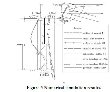
Part of computational results is shown in Figure 5. At depth of H = 4.1m, maximum horizontal displacement in soil nailing wall reaches to 19.7mm. At H = 10.6m, horizontal displacements in crest and the toe are 32mm, 22mm, respectively. In crest, settlement is equal to 22mm.The maximum horizontal displacement is 32mm near the base of pit. It can be found out that the deformation computed in the combined structure has very close to the values of monitoring results on September 23, 2007. Maximum bending moment in pile is calculated to be equal to 409.6kN.m, very close to values of the measured data, too.
CONCLUSIONS
The earth-retaining structure is subjected to the earth pressure, which is related to many factors such as soil elasto-plastic states, strength, stress-related path as well as structure own stiffness. Deformation and earth pressure in the combined structure are discussed in this paper to regard it as a whole. Within the combined structure, soil nailing wall and pile interact to bear earth pressure. For example, due to effect of the pile, the facing in soil nailing wall is subjected to the earth pressure much reduced. On the contrary, due to the existence of soil nailing wall, the passive earth pressure to pile becomes larger. In the combined structure, the distribution of earth pressure is inconsistent with that from Rankine theory. based on numerical simulation results, the depth of excavation in the active zone is found to divide into three sections. Coefficients of active earth pressure are adjusted to meet the results of simulation each section.
REFERENCES
Bridle, R. J.(1989) “Soil nailing—analysis and design”, Ground Engineering, Vol. 22(6): 52–56
Craig R.F. (2002) Soil mechanics ( 6th edition), Spon press
Hashash, Y.M.A., and Whittle, A.J.(2002). “Mechanisms of load transfer and arching for braced excavations in clay”, J. Geotech. Eng., Vol. 128(3): 187-197
Yang, Y., Yuan, J. (1998) “Limit equilibrium method of soil nailing walls in deep excavation”, Geotechnical Investigation and Surveying, (6): 9-11
Yuan, J., Yang Y., Tham,L.G., Lee P.K.K. and Tsui Y. (2003), “A new approach of limit equilibrium and reliability analysis of soil nailed walls”, International Journal of Geomechanics, ASCE, Vol.3( 4): 145 -151
组合支护结构和在基坑工程中的应用
杨育文
(武汉市勘测设计研究院,汉口万松园路209号,430022)
摘要:土钉墙维护浅层土稳定,内支撑桩排维护整体稳定, 这种组合支护方式已在大型深基坑工程中广泛采用,但是在计算分析中一般没有将它们作为一个整体的空间结构来分析,这与实际情况是不相符合的。为了探讨这种组合支护方式的空间受力与挡土机理,采用数值模拟实验方法并结合实际工程进行研究,提出了组合支护整体刚度系数的新概念。分析结果表明了组合支护受到的土压力与Rankine土压力不相同,文中提出了修改建议等。获得的结论在一实例中得到了检验。
前言
本文中组合支护方式指土钉墙加内支撑:土钉墙维护浅层土稳定,内支撑桩排维护整体稳定。这种组合支护的使用条件:浅部杂填土强度较高,基坑周边建筑物或地下设施离开挖面相距较近,基坑顶部杂填土范围内土体用土钉墙维持稳定,而下部较软弱土层则采用内支撑桩排支护,限制土体位移,防止过大位移引起相邻构筑物破坏。
针对土钉墙稳定和变形分析,国内外学者已发展或应用多种不同方法,其中, 极限平衡法应用最广泛。内支撑桩排是一种传统的支护方式,弹性抗力法在工程中应用较普通。作为组合支护,它们一起发挥挡土作用,挡土机理是不同的。上部土钉墙挡土,下部桩排可以设计得短一些。同时,下部桩排维护了土钉墙的稳定。本文采用FLAC软件,对这一组合支护方式进行数值模拟分析,探讨基坑开挖过程中它的变形、土体中应力、土压力等大小及开挖过程中发生的变化,结合一基坑工程实例来分析其挡土机理等。
数值模拟
假设条件
在土钉墙内支撑桩排组合支护中,土钉、喷锚面层与桩排、锁口梁、内支撑组成的一个空间结构,作为整体来承受土压力和限制土体变形,是一个非常复杂的空间结构问题。为了减少计算工程量,合理简化问题,考虑主要影响因素,突出主要受力特点,在下面的模拟分析中,引入以下假设条件:
(1)土钉墙内支撑桩排组合支护作为均质土中的平面应变问题;
(2)不考虑锁口梁受力,内支撑与桩顶直接相连;
(3)除了土体按弹塑性考虑外,所有结构单元假设为弹性体;
(4)地面不存在超载;
(5)不考虑地下水的影响。
锁口梁主要作用是将相邻桩排连接在一起,整体受力,将内支撑推力传递到各个桩顶,它几乎不直接发挥挡土作用。另外,在下面数值模拟中模拟厚度内只存在一根桩。因此,不考虑锁口梁对计算结果影响不大。
单元选择
表1给出了支护结构组成与所选择的单元类型。土钉细长,柔性大,可选择杆单元模拟;土钉墙面层一般100mm厚,面积大,它与主动区土体在发生较大变形时可能会分离,存在耦合作用,用衬垫单元模拟较合适;钢筋混凝土内支撑与锁口梁浇筑(锁口梁和桩排浇筑)在一起,可用梁单元模拟;桩排与土体间存在相互耦合作用;土体采用几乎是正方体的六面体单元,可以提高计算精度。各结构单元基本情况:梁单元,两结点直线单元,可承受轴力、剪力、弯距;杆单元,两结点直线单元,只承受轴力,与周围土体通过摩阻力相互作用;桩单元,两结点直线单元,类似于梁单元,还可以与周围土体发生法向、切向耦合作用,与周围土体分离或闭合;衬垫单元,三结点平面单元,可与相邻土体发生切向、法向作用,与周围土体弹性连续,根据Mohr-Coulomb屈服准则,可与土体脱开或发生滑动。
数值模拟中充分考虑具体施工步骤与方法。如顶部土钉墙,边开挖、边插入土钉、边喷射混凝土形成面层; 基坑上部开挖到位后,设置下部桩排内支撑。土层采用分层开挖模拟,第六步开挖前设置桩排,第七步开挖前设置内支撑。
模拟范围
图1所示为宽度50m均质土长方形基坑,最终开挖深度10m,采用土钉墙和桩排支护。分10层开挖,每次开挖1m深度。对上部倾斜45°坡角土钉墙,每步开挖完成后即设置该层土钉和喷射面层。假设为平面应变问题,厚度取2.0m,模拟范围50m×30m,最终开挖深度以下取20.0m(见图1)。模拟范围内,包括一根桩、一排土钉、一个内支撑。
计算参数的选择
图1表示出了土体几何尺寸、部分计算参数值、土钉墙和内支撑桩排相对位置。下面分别介绍计算过程中所采用的其它参数值,它们基本上和实际情况相符。
(1)土钉墙。计算厚度内一列土钉,长5m,土钉空间布置SV×SH= 2.0×1.5m2,材料为Φ22钢筋,E=2×10⁸kPa,屈服强度fy=1.86×10⁷kPa。土钉与水平方向成15°倾角。灌浆孔径D=0.12m,灌注水泥砂浆,强度C20,土钉与周围土体间极限摩阻力 =15KPa。土钉墙面层由布置钢筋网和C20喷射混凝土组成,为弹性体,E=2.55×10⁷kPa,=0.25,厚100mm。面层与土体交界面上法向与切向刚度均为100KPa/m,粘结强度2kPa。
(2)桩排。计算厚度内存在单桩,直径1000mm,桩中心距2.0m,C30混凝土,弹模和泊松比大小如图1所示。它的土体之间切向和法向刚度分别为100KPa/m、10000KPa/m、粘结力10kPa、摩擦角20°。
(3)内支撑。计算范围内一个支撑,假定给20根桩提供支撑力。内支撑矩形截面,尺寸500×700mm2,C20混凝土,弹模2.55×10⁷kPa,泊松比0.25。
计算结果
图2所示为开挖深度H=5m、10m时,基坑地表沉降δV,在开挖面处沿深度方向水平位移δH分布图。当H=5m时,最大水平位移位于坑底以下,δHmax=25mm,最大沉降δvmax位于边界上,δvmax=15mm;当H=10m时,δHmax在坑底附近,δHmax=70mm,最大沉降δvmax=35mm,同样位于边界上。随着开挖深度的增加,土钉墙变形增加,但分布形状类似。最大水平位移并没有象预期的那样发生在地表,而是出现在基坑底附近,这是由于土体强度较低,出现了坑底隆起现象。不同开挖深度,桩排与土钉墙两者变形都存在协调性,桩排变形增加,土钉墙发生的位移也加大。
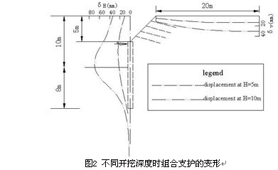
图3表示的是开挖深度H=5m,10m时,作用于土钉墙面层和桩排上的土压力系数分布图, K0-静止土压力系数,K0=0.7;Ka-主动土压力系数,Ka=0.49;Kp-被动土压力系数,KP=2.04;σH5、σH10分别表示H=5m、10m时开挖面水平方向的应力; 、 分别表示支护结构后面和前面土体自重应力,其中 从基坑顶部地表算起, 从坑底H=10m处算起。
对内支撑桩排支护,Teriaghi和Peck提出了半经验公式计算内支撑上的荷载[13]。对本文介绍的组合支护,它的工作性状要比一般的内支撑复杂一些。由于桩顶处内支撑约束了支护体系向坑内的变形,附近土体可能没有进入塑性状态,这时Rankine土压力理论是不适用的;在靠近开挖面附近,受桩顶处内撑影响较小,桩排向坑内变形较大,该范围主动区土体则有可能进入塑性状态,适合Rankine土压力理论应用条件;靠近桩下端附近,由于土体的嵌固效应,限制了主动区土体变形,同样Rankine土压力不适用。数值模拟结果表明(如图5所示),H=5m时,开挖面附近土钉墙面层上的土压力接近Rankine主动土压力,而上部则较小。随着开挖深度的增加,由于下部的内支撑桩排限制了主动区土体的位移,土钉墙面层受到的土压力反而有所减少,如图5所示。 当H=10m时,开挖面附近土压力系数接近Rankine主动土压力系数,而支内撑桩、桩下端附近则较大。因此,对于图5所示的支护体系,可将主动区分成三段: ab、cd、ef,被动区以gh段表示,它们的土压力系数分别修改如下:
典型基坑工程实例分析
基坑概况和实测数据
江花办公住宅综合楼北临三阳路、东临中山大道、西临京汉大道一高层建筑,总用地面积2.34公顷,由1栋13层、1栋15层、1栋2层办公楼以及3栋18层住宅楼组成。6栋拟建建筑物在平面布局上组成类似于“四合院”型,拟设置2层满铺地下室,基础埋置深度10.60m。地下室形状呈长方形,基坑周长约516m,面积约14400m2,开挖深度9.4~10.6m。基坑北侧、东侧存在地下水管或光缆,距基坑边线一倍开挖深度以内,基坑周边不允许有较大变形。以位于三阳路侧fa段土层情况为例说明场址土层结构。与支护相关的土层从上到下是(1)杂填土层,表层土; (1-2)素填土;(2-1)粉土夹粉质粘土;(2-2)粉质粘土;(3)粉土互层;(4-1)粉砂夹粉土;(4-2)粉砂,厚度d>5m。场址存在上层滞水,赋存于表层填土层,地下承压水存在于第四土层单元砂层中。施工中采用深井降水,将承压水降低至开挖坑底面以下2m处,上层滞水采用封堵法,用6m长粉喷桩沿基坑四周布置。基坑采用桩排加内支撑支护方案,为了降低桩内弯矩,将上面4.1m的高度土层进行卸载成平台,该范围土坡用土钉墙加固,与内支撑桩排支护结合在一起使用。由于基坑周边土层分布存在差异,支护方案有一定变化,沿周边分成六段,其中fa段设计剖面如图6所示。
江花基坑工程开挖深,地质条件复杂,基坑周边紧邻重要构筑物,开挖时恰逢雨季,是武汉地区特大型基坑工程。在开挖过程中,采用信息法施工。图6中表示出了在2007年9月23号终止开挖深度10.6m时fa剖面附近E5号桩排实测弯矩图以及该桩附近C7号测斜孔水平向位移图:最大弯矩390kN•m,最大位移26mm,两者都位于坑底附近,测得土钉墙顶部和墙趾水平位移分别为39mm、26mm,基坑顶部沉降18.1mm。
计算分析
将fa段基坑作为计算分析对象。计算中采用的假设条件除了将均质土改变为多层土以外,其余与本文第1节中介绍的六个假设条件基本一致。计算中,不考虑用作挡水的沿基坑四周布置的粉喷桩的作用。
基坑近似长方形,长185.8m,宽96.9m,fa段位于长边靠中间位置上,分析中沿长边取1.2m厚作为平面应变问题考虑。模拟范围100m×35m: 坑内50m,坑内50m,最终开挖面以下取24.4m。分11层开挖,前10次每次开挖1m深度,最后一次开挖0.6m。对上部土钉墙,每步开挖完成后即设置该层土钉和喷射混凝土面层,开挖第四步后设置桩排,第六步后加内支撑。
各土层计算参数值如表2中所示,图6表示出了土层厚度、基坑几何尺寸、土钉墙和内支撑桩排相对位置,下面分别介绍计算过程中与土钉墙、桩排相关的参数值。
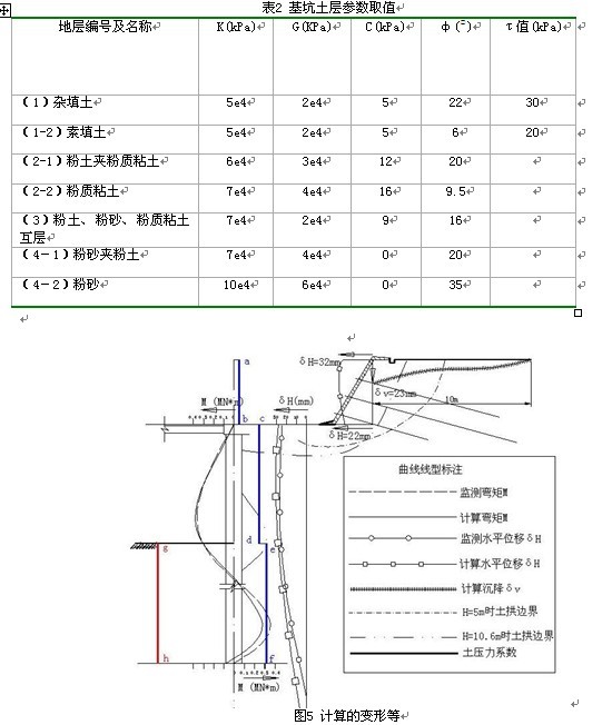
计算部分结果如图5所示。当H=4.1m时,土钉墙水平方向最大位移19.7mm。 当H=10.6m,土钉墙坡顶和墙趾水平方向位移分别是32mm、22mm,基坑顶部沉降22mm,沿桩身方向最大水平方向位移32mm,位于坑底附近,形状如图8所示。由此可以看出,组合支护变形计算值与2007年9月23号监测结果比较接近。
计算桩身最大弯矩409.6kN.m,形状如图8所示。与监测数据比较可知,计算值与实测数据接近。
结 论
支护结构受到的土压力与附近土体的弹、塑性状态、强度以及它本身的刚度、位移、应力路径等多因素相关。本文介绍的组合支护结构数值模拟则能将它们作为一个整体考虑。由于桩排顶部一方面受内支撑的约束,另一方面受上部土钉墙的影响,显然不符合Rankine土压力理论的适用条件。因此,这种组合支护变形特征、挡土机理等有待进一步的探。通过以上讨论,土钉墙内支撑组合支护受到的土压力沿深度方向变化复杂,与Rankine土压力大小、分布都不一致。本文根据数值模拟结果,提出了沿深度方向将主动区土压力分成三段分别计算土压力系数、对Rankine被动土压力系数打折的建议,对实际工程有较好的参考价值。